
Can be used to switch high-current (up to 800mA) loads.Note that the motor here draws about 500mA from the 12V power source, since the 2N2222 has a collector current rating up to 800mA this circuit is possible had it been a BC547 the transistor should have been burnt. I have used a base voltage of 5V and a value of 1K as the current limiting resistor. In actuality circuit modifications might be required. To make things simple, I have shown a simplified circuit to make a transistor switch. The value for this resistor can be calculated using the formula R B = V BE / I B As the name suggests this resistor will limit the current flowing through the transistor to prevent it from damaging. However, one important thing to notice is the Base resistor a.k.a current limiting resistor. This transistor will make it forward-biased and thus close the connection between the collector and emitter. The Base-Emitter voltage of this transistor is 6V so you just have to supply this voltage across the base and emitter of the transistor to induce a base current into the transistor. Size:138K microsemi 2n2222aubc. This transistor like all can be used either as a switch or as an amplifier. So if you looking for an NPN transistor that could switch loads of higher current, then 2N2222 might be the right choice for your project. 2N2222 can allow collector current up to 800mA and also has a power dissipation of 652mW which can be used to drive larger loads than compared with BC547. 1 X 2N2222 transistor (or any similar Hello, guys today I am going to. But there are two important features that distinguish both. SMD optocoupler isolation, strong drive capability, stable performance trigger. The 2N2222 transistor is very much similar to the commonly used NPN transistor BC547. When the base current is removed the transistor becomes fully off, this stage is called the Cut-off Region, and the Base Emitter voltage could be around 660 mV.

This stage is called Saturation Region and the typical voltage allowed across the Collector-Emitter (V CE) or Base-Emitter (V BE) could be 200 and 900 mV respectively. When this transistor is fully biased, it can allow a maximum of 800mA to flow across the collector and emitter. To bias a transistor we have to supply current to the base pin, this current (I B) should be limited to 5mA. The maximum amount of current that could flow through the Collector pin is 800mA, hence we cannot connect loads that consume more than 800mA using this transistor. 2N2222A has a gain value of 110 to 800, this value determines the amplification capacity of the transistor. 2N2222 Brief DescriptionĢN2222 is an NPN transistor hence the collector and emitter will be left open (Reverse biased) when the base pin is held at the ground and will be closed (Forward biased) when a signal is provided to the base pin. However there are no JEDEC police, as far as I know and most parts that are called 2N2222 are more like PN2222 (TO-92 packaged), with less thermal performance and not hermetic. Note: Complete Technical Details can be found in the 2N2222A datasheet, given at the end of this page. The 'real' 2N2222 is packaged in a hermetic TO-18 metal can and has the best thermal capability.
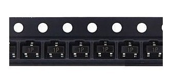
2n2222 transistor smd how to#
Just to make sure I understand how to pick the right one, I'm looking at Vgs for IRLML2502 ( ) and it says: max Vgs at 4.5V is 4.2. N025P (which actually gives results for IRLML2502 on ebay) Interestingly, a SI2302 a N025P and a IRLML2502 are equivalent. I have seen a few mosfet circuits placing the load between the fet and the ground. High side, however that's what I tend to do naturally and I am not really familiar with the ups and downs of each setup. How are you switching the power to the servo, high side or low side switching?


 0 kommentar(er)
